Power-Supply Management Solution for PCI Express x16 Graphics 150W-ATX Add-In Cards
Abstract: The PCI Express x16 Graphics 150W-ATX Specification establishes detailed power-supply management requirements for PC-graphics add-in cards. Designing a discrete solution to satisfy these requirements can add considerable cost and complexity to the overall card design.
This application note describes how to use the MAX5943 integrated current limiter and the MAX5944 low-drop power-supply ORing switch controller to enable a small, simple, low-cost power-management solution for PCI Express 150W graphics cards.
The Specification
PCI Express is the next revolution in graphics add-in card-interconnect standards. This specification, significantly increases bandwidth between the central processing unit (CPU) and graphics processing unit (GPU) by enabling a balanced distribution of bandwidth to those applications that require it the most. The PCI Express x16 Graphics 150W-ATX Specification provides additional electrical power for PCI Express graphics beyond that supported by the existing PCI Express x16 specifications. The new maximum power levels supported by this specification are 25W (low-profile card), 75W (standard size), and 150W.
A PCI Express x16 Graphics 150W-ATX add-in card can draw a maximum of 75W through the standard connector, as specified in PCI Express CEM 1.1. Up to 75W additional power is provided through a 6-pin wire-to-board connector. Therefore, the maximum total power that must be provided to a PCI Express x16 Graphics 150W-ATX add-in card is 150W.
A PCI Express x16 Graphics 150W-ATX add-in card must adhere to strict power-distribution, power-up, and power-consumption requirements. To ensure safe operation and compatibility with noncompliant installations, the following power-management requirements must be met:
- The +12V delivered from the standard x16 connector and the additional +12V delivered from the dedicated 6-pin power-supply connector must be treated as coming from two separate system power-supply rails.
- The two +12V input potentials must not be electrically shorted at any point on a PCI Express x16 Graphics 150W-ATX add-in card.
- No specific power sequencing between the slot and 6-pin connector can be assumed. A PCI Express x16 Graphics 150W-ATX add-in card must handle all possible combinations.
Two-Chip Solution Meets the Specification
Designing a power-management system that satisfies all these requirements from discrete components can add considerable cost, complexity, and size to a PCI Express graphics card. Fortunately, the MAX5943 and MAX5944 integrated circuits make it possible to easily meet all the specified functional requirements. These integrated circuits, moreover, provide additional protection features such as soft-start, active current limiting, undervoltage lockout, and electronic circuit-breaker function. All this capability is achieved with minimal forward-voltage drop and power loss.
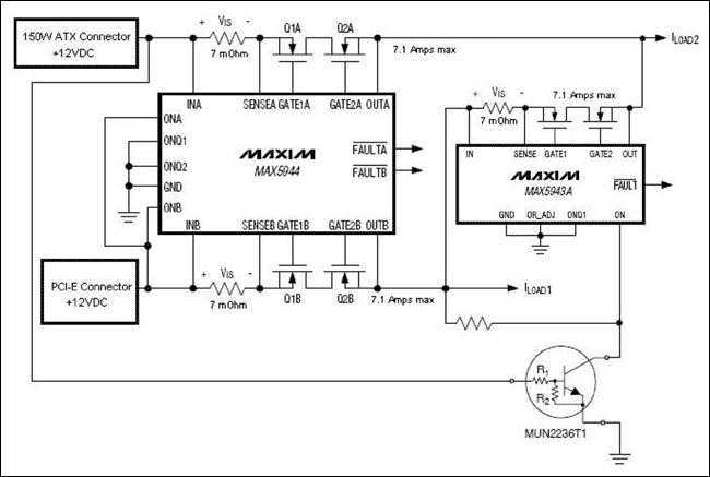
Figure 1 is a 150W-ATX graphics power-management solution that uses the MAX5943A and MAX5944 integrated circuits. This solution ensures that power from the two 12V supply connectors are never shorted together. It also allows power from the x16 connector to be routed to the loads that would otherwise be powered from the 150W-ATX 6-pin power connector, in case the 150W-ATX connection is not established. This solution, however, prevents the graphics card from starting when it is not fully plugged into the PCI Express connector, or if the PC motherboard is not powered.

Figure 1. 150W-ATX compliant graphics power-management solution using the MAX5943A and MAX5944.
Connecting the MAX5944's ONA and ONB to the x16 connector 12V supply ensures that the graphics add-in card will not power up unless it is installed in a powered PCI Express x16 slot, even if the 6-pin 150W-ATX connector is connected and powered. This prevents the card from accepting 12V power solely from the 150W-ATX connector, thereby protecting the graphics card and PC motherboard from damage that could occur from improper installation.
When 12V power is present at the x16 connector, the MAX5944 will slowly enhance n-channel transistor Q2B, limiting in-rush current. The startup current initially flows through the body diode of Q1B. When the current to the card exceeds 714mA, the voltage drop across the 7mΩ sense resistor exceeds VOR = 5mV, and Q1B is enhanced to drastically reduce voltage drop and power loss.
If the current from the x16 connector exceeds the ILIMIT value of 7.14A (set by the 7mΩ sense-resistor value), the MAX5944 will reduce the voltage at the gate of Q2B to regulate the maximum current at ILIMIT. If the current overload continues for more than 2ms, the MAX5944 pulls down strongly on the gate of Q2B, disconnecting the faulty load from the system power supply. An active-low output, FAULTB, will be asserted to indicate that a load fault occurred. If the current overload does not last more than 2ms, the MAX5944 returns Q2B to fully enhanced operation.
While power is present at the x16 connector only, the MUN2236T1 bias-resistor transistor does not conduct, and the MAX5943A's ON pin is allowed to rise with the 12V rail from the x16 connector. This causes the MAX5943A to cross-connect x16 power to the loads normally assigned to the 150W-ATX connector. The MAX5943A implements the same soft-start and current-limit/circuit-breaker functions as the MAX5944. Increasing the value of the current-sense resistor used with the MAX5943A allows tailoring of the maximum current limit for ILOAD2 when the 150W-ATX connector is not powered. Thus, power delivery can be apportioned between ILOAD1 and ILOAD2 in reduced-power operating modes.
When 12V power is present at both the x16 connector and the 150W-ATX 6-pin connector, the MAX5944 controls power from both supplies in the same manner as described for the x16 connector. Current from each connector is individually limited to 7.14A, corresponding to about 85W at 12V (75W plus 15% margin). In addition, the MAX5943A will prevent cross-connection of the two power-supply rails, because the MUN2236T1 bias-resistor transistor will pull down on the MAX5943A's ON pin, keeping GATE1 and GATE2 low. This function satisfies the requirement to treat the two connectors as separate supply rails.
Simple One-Chip Solution for Reduced Cost
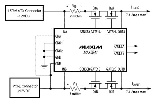
If a simpler implementation is desired and the graphics card can be operated in reduced power modes without supplying current at ILOAD2, the MAX5943A can be omitted. Figure 2 shows this lower cost implementation.

Figure 2. Low-cost 150W-ATX graphics power-management solution using only one MAX5944.
In this power-management solution, the MAX5944 functions identically to the implementation shown in Figure 1, but ILOAD2 cannot be supplied from the PCI Express connector. This reduces the cost and size of the power-management solution by eliminating one IC and its external components. This approach does, however, impose some design constraints on the graphics system for reduced power operation because power cannot always be delivered to ILOAD2.
One should note that additional gating conditions can be applied at ON, ONA, and ONB in the circuits of Figures 1 and 2. These conditions can be used to assert positive system control of the 150W-ATX graphics card power.
Three-Chip Solution Maximizes Power-Management Options
If a truly customizable power-management solution is needed, the MAX5944 in Figures 1 and 2 can be replaced with two MAX5943 ICs, one for control of ILOAD1 and one for ILOAD2. Unlike the dual-channel MAX5944, the single-channel MAX5943 includes several additional configuration inputs: TIM, ILIM, LATCH, and OR_ADJ. These pins allow adjustment of functional parameters such as current-limit/circuit-breaker timeout, current-limit/circuit-breaker threshold voltage, latched or autoretry fault management, and the ORing switch turn-on threshold voltage. This is a more elaborate solution, but features greater flexibility in the overall graphics-card power management. Table 1 shows the ranges of adjustable timeout periods available in different versions of the MAX5943 integrated circuit.
Table 1. MAX5943 Timeout Periods
| PART |
DEFAULT TIMEOUT TIM = IN(ms) |
PROGRAMMABLE TIMEOUT RANGE
(4kΩ < RTIM < 50kΩ) |
MAXUM TIMEOUT TIM = FLOATING (ms) |
| MAX5943A |
2 |
1.04ms to 11.05ms |
12.5 |
| MAX5943B |
0.5 |
32.5µs to 345µs |
4.8 |
| MAX5943C |
1 |
65µs to 690µs |
9.6 |
| MAX5943D |
2 |
130µs to 1.38ms |
19.2 |
| MAX5943E |
4 |
260µs to 2.76ms |
38.4 |
References
- Data sheet for the MAX5943 FireWire Current Limiter and Low-Drop ORing Switch Controller
- Data sheet for the MAX5944 Dual FireWire Current Limiter and Low-Drop ORing Switch Controller
- PCI-SIG, PCI EXPRESS X16 GRAPHICS 150W-ATX SPECIFICATION, REV. 1.0, October 25, 2004.